

How To Install A 240v Gfci Circuit Breaker
Single Phase and 3 Stage RCD and GFCI Wiring Circuit Diagrams and Installation
GFCI or RCD or RCCB or ELCB?
- GFCI is the abbreviation of "Ground Fault Circuit Interrupter"
RCD & RCCB
- RCD is the brusque form of "Residual Current Device"
- RCCB is also known as "Residual Current Circuit Breaker".
GFCI and RCD or RCCB are same.
In America, it is unremarkably known every bit GFCI "Ground Fault Excursion Interrupter" or "GFI "Basis Fault Interrupter" or ALCI "Appliance Leakage Current Interrupter".
In Europe and Commonwealth of australia, the same affair is known as RCD "Residuum Electric current Interrupter" or RCCB "Residual Current Circuit Billow" or if overcurrent protection device such as MCB is used with combination of RCD i.east. RCD + MCB, then it is known as RCBO "Residuum Electric current Circuit Breaker with Overcurrent Protection". They are also known as safe switches. RCD may be divers equally Current Operated ELCB which is known asRCCB.
ELCB stands for "Earth Leakage Circuit Billow" and it has been replaced with the latest RCD device due to some of ELCB disadvantages (as it works on proper world connection).
- Related Mail service: Divergence Between MCB, MCCB, ELCB & RCB (RCD or RCCB) Circuit Breakers
GFCIs and RCDs are used to protect against electric shock in case of basis faults and leakage currents and trip the excursion. Co-ordinate to IEC and NEC, information technology is must to use and install these devices in watery areas similar laundry, kitchen, spa, bath and other outdoor installation.
Now, you have got the thought as nosotros are going to show different wiring circuit diagrams for unmarried pole, 2 poles, three poles and four poles (both single phase and three phase) RCD (RCCB) or GFCI circuit breakers.
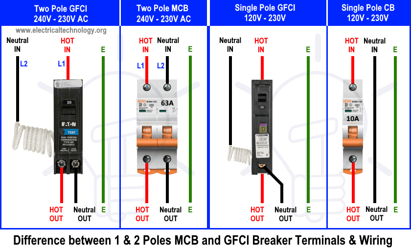
Go on in mind that the the difference between single pole and 2 poles normal circuit breakers and a GFCI is that there is a builtin white wire on the back side of GFCI and it must exist continued to the neutral busbar in the mains supply or it will not work and protect the circuit properly. Additional, you may read the difference between GFCI and AFCI in the previous mail.
- Related Post: GFCI: Ground Fault Excursion Interrupter. Types, Working & Applications
Wiring a Single Pole GFCI Excursion Breaker
The post-obit wiring shows an ordinary outlet has been wired and protected through single phase single pole GFCI excursion breaker.
The builtin white wire in the footing fault circuit interrupter excursion breaker should be direct connected to the incoming supply neutral bar in the abode mains distribution board or it will not work otherwise.
The Line (Hot, Live or Phase) is directly connected to the GFCI input and the output is connected to the line terminal of ordinary outlet / receptacle. The GFCI breaker load neutral has been connected to the load terminal of outlet. The ground terminal of outlet is connected to the ground bar in the mains distribution lath.
This style, this 15-16A, 120V outlet is GFCI protected by 20A GFCI breaker and information technology is recommended to use it in the watery areas like bathrooms, kitchen, spa and other outdoor applications.
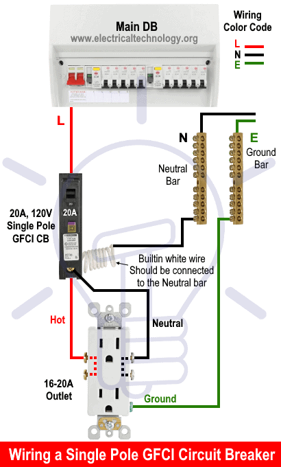
The same wiring tin can exist done for 230V, 13A circuit using the correct wire size, proper circuit breaker rating and suitable rating of switches and outlets.
- Related Postal service: How to wire a GFCI Outlet? – GFCI Wiring Circuit Diagrams
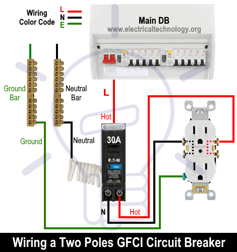
Wiring a 2 Poles GFCI Circuit Breaker
The following wiring shows an ordinary outlet has been wired and protected through a double pole GFCI circuit breaker.
Same like above wiring diagram for 1-Pole GFCI CB, the builtin white wire on the dorsum side of GFCI must be continued to the neutral bar in the main DB. The Input is connected to the hot wire from Main MCB. The two wires as output (hot and neutral) are continued to the line terminals of ordinary outlet.
This way, this 24 amp, 120V ordinary outlet is protected by the 30 amp GFCI excursion breaker.
In case of 230V and 240V, the aforementioned wiring diagram should be follow expect but one line (Fifty1 or L2) should be connected as hot to the input concluding of GFCI.
- Related Post: How to Wire GFCI Philharmonic Switch and Outlet – GFCI Switch/Outlet Wiring Diagrams
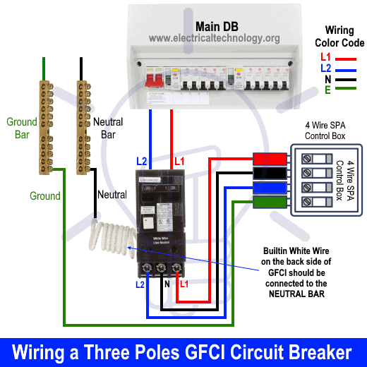
Wiring a Three Poles GFCI Excursion Billow
The post-obit wiring shows hot h2o tub spa or whirlpool spa has been wired and protected through a 3 pole GFCI circuit breaker.
As we know that in 240V, there is no need to connect the neutral, simply in some cases the appliances should be connected to the neutral according to the needs provided by the manufactures and user manuals.
This is a 4 wire GFCI wiring diagram. Equally mentioned higher up, the builtin white wire has been connected to the neutral busbar in the main DB. 2 Lines from primary distribution lath MCB as L1 and 502 (Unmarried Stage 240V) has been connected to the input of GFCI.
As shown in the fig, the three output terminals has been connected to the SPA command box followed past the printed marking i.east. the middle concluding is Neutral and the first and last one is two lines i.eastward. L1 and L2. At last, the ground wire from basis busbar has been connected to the ground concluding in SPA control box.
- Related Mail: Wiring of the Distribution Lath with RCD (Balance Electric current Devices)
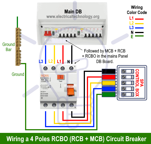
Wiring a Four Poles RCBO or GFCI Circuit Breaker (Three Phase RCCB Wiring)
The iii phase wiring for GFCI or RCD (RCCB) or RCBO wiring diagram shows the three lines (L1, L2 and L3) and neutral has been continued equally input to the RCCB from Main lath followed by MCB i.eastward. overcurrent protection.
The lower 4 terminals and footing wire of RCBO has been connected to the spa control box by the following sequence. Blood-red (L1), Yellowish (L2), Blue (L3), Black (Neutral) and Green/Yellow (Ground / World).
The following diagrams shows the three phase four poles RCBO (RCB + MCB) circuit billow to control and protect hot h2o spa.
In case of three phase spa wiring, use 12 or 10 gauge wire size for each line. For instance, use 12# or iv.0mmtwo wire for up to 12kW, 3 phase 415V – 480V where the max current is 18.2A. Use 8# or 6.0mm2 wire for the aforementioned 12kW spa three phase 208V where the max current is 33.iii amp. In case of college wattage, use the proper wire size according to the table and use manual.
Precautions:
- Switch off the main circuit breaker to brand sure the ability supply is OFF before wiring a GFCI outlet.
- Apply the suitable voltage and ampere rating of switch with appropriate wire size and proper size MCB according to the load rating.
- Use the correct polarity i.due east. verify the Load and Line terminals while installing a GFCI for protection. In other words, connect the wires to the correct side of outlet for proper functioning.
- Regular maintenance, check and test is recommended while test the portable GFCI before each operation.
- Contact the authorized and licensed electrician for GFCI installation if you lot are not sure about the wiring diagrams.
- We have used Cherry-red for Hot or Line 1, Xanthous for Line 2, Bluish for Line 3, Blackness for Neutral and Green for Ground for analogy purpose only. Follow your ain surface area wiring colour codes co-ordinate to NEC, IEC etc.
- The author will non exist liable for any losses, injuries, or damages from the display or utilise of this information or if you lot try whatsoever excursion in incorrect format. And then please! Be careful because it'south all virtually electricity and electricity is too dangerous.
Related Wiring Installation Diagrams and Tutorials:
- Single Phase Electric Wiring Installation in Home – NEC & IEC
- 3 Phase Electrical Wiring Installation in Home – NEC & IEC
- How to Wire Auto &# Manual Changeover & Transfer Switch (i & 3 Stage)
- Single-Phase Electrical Wiring installation in a Multi-Story Building
- Three-Phase Electrical Wiring installation in a Multi-Story Edifice
- How to Wire 120V Simultaneous H2o Heater Thermostat?
- How to Wire 240V H2o Heater Thermostat – Not-Continuous?
- How to Wire iii-Stage Simultaneous Water Heater Thermostat?
- Even More than Electric Wiring Installation & Tutorials

Source: https://www.electricaltechnology.org/2020/04/gfci-circuit-breaker-wiring.html
Posted by: widemanwhibelf.blogspot.com
0 Response to "How To Install A 240v Gfci Circuit Breaker"
Post a Comment